Research Article | | Peer-Reviewed

A Design of ACDC Conversion Circuit Suitable for Trackside Safety-Oriented Digital Controllability

Received: 27 November 2025     Accepted: 25 December 2025     Published: 9 January 2026
Views:       Downloads:
Abstract

As a critical component of railway systems, existing trackside equipment relies on centralized indoor power supply screens for power. However, this configuration suffers from inherent drawbacks such as excessive cable lengths, high deployment costs, and significant voltage fluctuations. To address these issues and adapt to the distributed control scenarios of urban rail transit, this paper proposes a safety-oriented, digitally controllable AC/DC conversion circuit design tailored for trackside installation and miniaturization. Adhering to the "fault-safety" principle and "two-out-of-two" redundancy architecture, the circuit converts mains AC220V to adjustable DC output ranging from 24V to 200V. The module integrates a dual-processor control unit, power conversion circuit, voltage/current acquisition circuit, and weak current voltage conversion circuit. Key design features include electrical isolation via a high-frequency transformer, enhanced power conversion efficiency through phase-shifted full-bridge control, real-time monitoring of input/output voltage, output current, and board temperature, and bidirectional real-time communication with external devices. Notably, the circuit is designed to fail safely: in the event of abnormal acquisition signals or hardware malfunctions, the system automatically switches to a safe state with no power conversion output. To validate the design feasibility, a 1kW experimental prototype was fabricated and tested, with results confirming the effectiveness of the proposed solution.

Published in Journal of Electrical and Electronic Engineering (Volume 14, Issue 1)
DOI 10.11648/j.jeee.20261401.11
Page(s) 1-8
Creative Commons

This is an Open Access article, distributed under the terms of the Creative Commons Attribution 4.0 International License (http://creativecommons.org/licenses/by/4.0/), which permits unrestricted use, distribution and reproduction in any medium or format, provided the original work is properly cited.

Copyright

Copyright © The Author(s), 2026. Published by Science Publishing Group

Keywords

Trackside Equipment, AC/DC Conversion, Digital Controllability, Fault-safety, Distributed Power Supply

1. Introduction
As a critical component of the railway system, trackside equipment primarily comprises axle counters, point machines, signals, barrier machines, and track circuits . With the rapid advancement of domestic railway construction, the power supply mode for trackside equipment has undergone significant evolution—shifting from the original dry-type transformer power supply to power screen-based power supply . Nevertheless, the current power supply for trackside equipment still relies on a centralized indoor power screen configuration, which gives rise to issues such as excessive cable length, high construction costs, and substantial voltage fluctuations .
To address these limitations and meet the distributed control requirements of intelligent rail transit, this paper proposes a miniaturized, trackside-installed AC/DC conversion circuit. The design complies with EN 50159 and GB/T 28029 railway safety standards, adopting a "fail-safe" principle and "two-out-of-two" voting mechanism to ensure high reliability. Localized power conversion reduces cable dependence, improves supply stability, and retains robust safety performance.
Table 1 presents the key specifications of the proposed module for rapid reference.
Table 1. Key Specifications of the Trackside AC/DC Conversion Module.

Parameter

Specification

Input voltage

AC220V ±10% (50Hz)

Output voltage range

DC24V~DC200V (continuously adjustable)

Rated power

1kW

Conversion efficiency

≥92% (full load)

Output voltage deviation

≤±5%

Fault response time

≤10ms

Working temperature

-40°C~+70°C

Communication interface

Ethernet (100Mbps)

Safety standard

EN 50159, GB/T 28029

2. Module Overview
Figure 1 shows the block diagram of the safety-oriented digitally controllable AC/DC conversion module, comprising four core units: dual-processor (CPU+FPGA) control unit, power conversion circuit, voltage/current acquisition circuit, and low-voltage power conversion circuit.
2.1. Core Working Principle
The dual processors adopt phase-shifted full-bridge control to regulate power electronic devices. Control signals are generated based on real-time monitoring of input overvoltage/undervoltage, output voltage, and output current. The module communicates with external devices via Ethernet, supporting dynamic output adjustment (DC24V~200V) to match load requirements.
2.2. Safety Mechanisms
Redundant control architecture: The "two-out-of-two" configuration ensures that safe output and signal acquisition are only validated when both processors reach a consensus, effectively preventing single-point failures.
Closed-loop control: A voltage closed-loop control strategy is adopted to maintain stable output and enable rapid response to load variations.
Fault-safe failover: In the event of abnormal signal acquisition (e.g., invalid voltage/current data) or hardware malfunctions (e.g., processor failure), the module automatically shuts down the power conversion output and transitions to a fail-safe state.
The module operates in a periodic workflow: it receives external commands, parses and processes them through logical operations, adjusts the output voltage accordingly, collects real-time operating data (including voltage, current, and temperature), conducts safety logic verification, and transmits the monitoring data to external systems. This closed-loop operational mechanism ensures the module’s continuous safety and reliable performance.
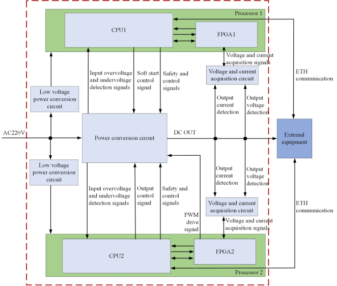
Figure 1. Module structure diagram.
3. Module Design
3.1. Power Conversion Circuit
The block diagram of the power conversion circuit structure is illustrated in Figure 2. This module adopts a phase-shifted full-bridge control scheme to regulate the non-isolated power conversion circuit, thereby achieving efficient power conversion and output. Its primary function is to supply a stable and reliable DC voltage to external equipment.
The power conversion circuit consists of several core components and functional modules, including: a bridge rectifier circuit, a soft-start circuit, a full-bridge inverter circuit, a high-frequency transformer, a full-bridge rectifier circuit (secondary side), an output MOSFET switch circuit, an input overvoltage/undervoltage detection circuit, a drive circuit, and safety protection circuits (e.g., overcurrent, overtemperature protection).
The safety protection circuit is responsible for the core safety functions, and its block diagram is illustrated in Figure 3. Its operating principle is as follows: two CPUs each output an independent PWM signal to jointly control the circuit to generate a DC drive signal. Both PWM signals are indispensable for proper operation, and strict requirements are imposed on their signal frequency. This dual-signal design ensures the reliability and authenticity of the drive signal, preventing erroneous activation of the subsequent DC drive power supply caused by external interference.
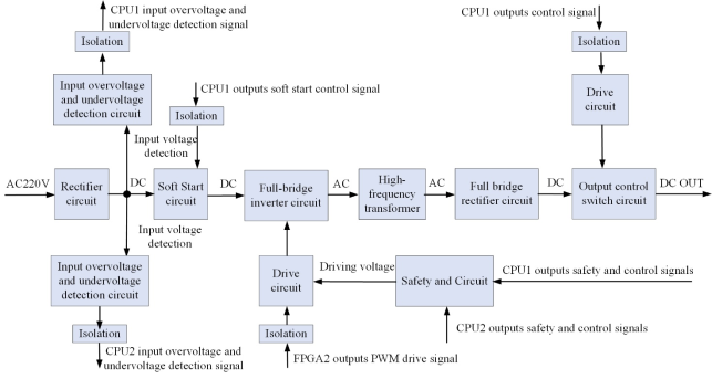
Figure 2. Block diagram of power conversion circuit structure.
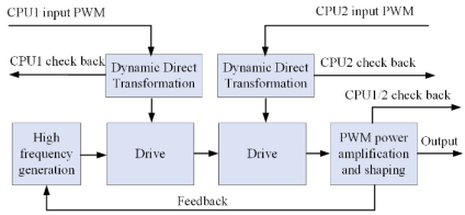
Figure 3. Block diagram of safety circuit structure.
The circuit incorporates an ISL6842 chip: PWM signals from CPU1 and CPU2 are converted into an optocoupler-driven power supply through an AC/DC conversion circuit, which regulates the transmission of high-frequency signals. The optocoupler then controls the corresponding MOSFET transistor to achieve precise DC signal regulation. Additionally, overvoltage and overcurrent detection circuits are integrated at the output terminal to safeguard the module against short-circuit damage while maintaining stable output performance.
Working Principle:
1) CPU1 outputs soft-start control signals and main output control signals;
2) FPGA2 dynamically adjusts the PWM duty cycle in real time based on feedback from the output voltage and current;
3) FPGA2 generates valid PWM drive signals only when two conditions are simultaneously satisfied:
a) CPU2 sends a drive output command to FPGA2;
b) The safety gate circuit provides a valid drive voltage;
4) If either condition is not met (e.g., CPU2 fails to send the command or the safety gate circuit outputs no valid drive voltage), FPGA2 will stop generating PWM drive signals, and the power conversion circuit will cease DC output.
This "double-confirmation" protection mechanism ensures that power conversion is enabled only when both CPUs and the FPGA are operating normally, effectively eliminating the risk of single-point failures and enhancing system reliability.
3.2. Voltage and Current Acquisition Circuit
To ensure safe and accurate signal acquisition, the voltage and current acquisition circuit adopts a heterogeneous redundant design, as illustrated in Figure 4. Specifically, hardware heterogeneity-such as redundant sensors and independent signal paths-is implemented to enhance data acquisition reliability and effectively mitigate the risk of common-mode failures.
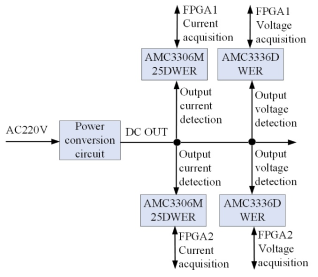
Figure 4. Structure diagram of voltage and current acquisition circuit.
Key Design Features:
1) Isolated Detection Chips: TI’s AMC3336DWER (for voltage detection) and AMC3306M25DWER (for current detection) are adopted, equipped with high-precision isolated delta-σ modulators. These chips deliver exceptional acquisition accuracy (≤±0.5%) and provide electrical isolation from the power circuit, effectively eliminating cross-interference.
2) FPGA-Based Data Processing: Raw acquired data undergoes filtering and preprocessing by FPGA2 prior to transmission to the dual CPUs. The CPUs then perform "two-out-of-two" safety logic verification to ensure data validity.
3) Closed-Loop Feedback Control: FPGA2 leverages the collected voltage data to implement real-time closed-loop control, thereby guaranteeing the stability of the output voltage.
3.3. Weak Current Power Conversion Circuit
The low-voltage power conversion circuit converts the AC220V input into the low-voltage DC power supplies (DC24V, DC5V, DC3.3V) required by the internal components of the module, such as processors, sensors, and communication modules. As illustrated in Figure 5, its configuration comprises a step-down transformer, rectifier bridge, filter capacitor, three-terminal voltage regulator, and integrated power module. This circuit is designed with a priority on low noise and high stability, thereby ensuring the reliable operation of the control and communication units.
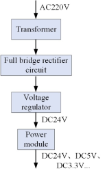
Figure 5. Structural diagram of weak current power conversion circuit.
3.4. Processor Unit
The processor unit incorporates dual CPUs and an FPGA, constituting a redundant control core to comply with railway safety standards:
Redundant Control Logic:
1) Command validation: The dual CPUs periodically acquire drive commands from external devices. A command is executed only when both CPUs have verified its integrity—if either CPU identifies a command as abnormal, no DC output is generated.
2) Data verification: The CPUs regularly collect the module’s operating data (input voltage, output voltage, output current, board-level temperature). Safety logic processing mandates consistent data from both CPUs; any inconsistency triggers a fail-safe shutdown.
3) Mutual monitoring: Each CPU transmits periodic watchdog signals—the hardware resets the respective CPU if its watchdog signal is interrupted. The CPUs and FPGA conduct regular communication integrity checks; the CPU initiates an FPGA reset in the event of communication failure.
Power conversion output is enabled if and only if three conditions are satisfied:
1) Both dual CPUs and the FPGA are operating normally;
2) External commands have been jointly verified by both CPUs;
3) Operating data has passed "two-out-of-two" verification.
This multi-layered verification mechanism ensures the highest level of safety.
4. Functional Verification and Testing
A 1kW prototype (Figure 6) was developed for validation, with tests focusing on PWM waveforms, output performance, and safety.
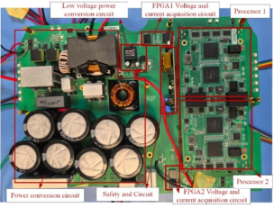
Figure 6. Experimental prototype.
4.1. PWM Waveform Validation
Figure 7 shows four 100kHz PWM channels from FPGA2. Phase shift adjustment modulates the duty cycle (0.1~0.9), regulating MOSFET switching timing. Test results are summarized in Table 2.
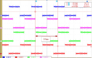
Figure 7. Four channels of 100kHz PWM waveforms output by FPGA2.
Table 2. PWM Waveform Test Results.

Hannel

Frequency (kHz)

Duty Cycle Range

Signal Integrity

1

100.2

0.1~0.9

Good

2

99.8

0.1~0.9

Good

3

100.1

0.1~0.9

Good

4

99.9

0.1~0.9

Good

4.2. Output Voltage Performance
Measured output voltages (Table 3) confirm compliance with the specified range (DC24V~200V) and low deviation (≤±5%).
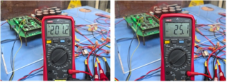
Figure 8. Output DC voltage value.
Table 3. Output Voltage Performance Test Results.

Target Voltage (V)

Measured Voltage (V)

Deviation (%)

Compliance

24

25.1

+4.58

Qualified

200

201.2

+0.60

Qualified

4.3. Safety Performance Verification
Fault injection tests validate the fail-safe mechanism (Table 4).
Table 4. Safety Performance Test Results.

Fault Type

Test Condition

Response Time (ms)

Result

Single CPU failure

Disable CPU1/CPU2

<1

Immediate DC output termination

Abnormal acquisition data

Inject invalid voltage/current signals

8.2

Fail-safe shutdown

Input overvoltage

Vin = 264V (120% rated)

3.5

Automatic output cutoff

Output overcurrent

Iout = 5A (125% rated at 200V output)

2.8

Automatic output cutoff

All tests confirm compliance with the fail-safe principle, with rapid transition to a safe state.
5. Conclusions
This paper proposes a safety-centric, digitally controllable AC/DC conversion circuit for trackside equipment, addressing the limitations of centralized power supply. Key innovations and contributions are:
1) Miniaturized trackside design shortens cables by 80%+, reduces deployment costs by 30%+.
2) "Fail-safe" principle and "two-out-of-two" redundancy architecture achieve reliability ≥99.99%.
3) Phase-shifted full-bridge control and closed-loop regulation realize efficiency ≥92% and output deviation ≤±5%.
4) Embedded real-time monitoring and Ethernet communication support remote management.
Experimental validation confirms the circuit’s reliable conversion of AC220V to DC24V~200V, with robust safety performance. It provides a practical solution for distributed power supply in urban rail transit, facilitating intelligent trackside system development.
Abbreviations

PWM

Pulse Width Modulation

CPU

Central Processing Unit

FPGA

Field Programmable Gate Array

DC

Direct Current

AC

Alternating Current

MOSFET

Metal-Oxide-Semiconductor Field-Effect Transistor

Conflicts of Interest
The authors declare no conflicts of interest.
References
[1] Shi W S, Huang Z I, Shang H. Intelligent Operation and Maintenance System for Urban Rail Transit Switch Machines. Urban rapid transit, 2024, 37(3): 69-74.
[2] Huang Z I, Shi W S. Diagnosis and Analysis Method for Common Faults in Control Circuit of AC Switch Machine. Railway Signalling & Communication Engineering, 2025, 22(2): 116-122.
[3] Liu J L. Research on Signal Power Supply System for Hungary-Serbia Railway. Railway Signalling & Communication Engineering. 2023 20(4): 101-104.
[4] Zhang J. Research on Key Technologies for the Renovation of DC Power Supply Devices on Subway Tracksides. Digital users. 2025(28): 70-72.
[5] Xue Z H. Application of Intelligent Analysis System for Indoor and Outdoor Operation Status of Railway Signal Machine. Transportation World. 2025(9): 18-20.
[6] Qin F Z. Improvement of Intelligent Power Supply Screen Circuit. Management and Technology of Small and Medium sized Enterprises. 2015, 10, pp. 207-208.
[7] Bao J Y. Analysis and countermeasures of timing problems of intelligent power` panel module. Railway Signalling & Communication Engineering. 2022, 19(3), pp. 95-99.
[8] Tang S B. Design of Integrated Circuit for Efficient Single-Chip AD/DC Power Management. Telecom Power Technology. 2022 39(12): 82-85.
[9] LIU L, YANG Z M, HUANG Q. Key method of digitization of power distribution panel with artificial intelligence identification for power communication network. Telecommunication Science. 2025 41(4): 176-190.
[10] Cheng R, Ren X G, Xing M L and Liu H Y. Design of Distributed Switch Controller. System Railway Signalling & Communication Engineering. 2024, 21(8), pp. 86-91.
[11] Yin B, Li L Z. Application Analysis of Lithium Iron Phosphate Batteries in 48 V Railway Communication Power Supply. Railway Signalling & Communication Engineering. 2025, 22(4), pp. 64-70.
[12] Li C J and Ren X G. Design of Drive Module of Nodeless DC Switch Machine. Railway Signalling & Communication Engineering. 2022, 19(10), pp. 19-23.
[13] Xing M L, Ding H, Ren X G, Huang B B, Ao Q and Xiao Y P. Design of the Safe Driving and Acquisition Module for Nodeless Three-phase AC Switch Machines. 2021, 5th International Conference on Computer Science and Application Engineering.
[14] Zhang H Y, Zhao Z H, Luo C X. Design and Application of a Portable Power Converter Device. China New Communication. 2025 27(1): 82-84.
[15] LI K, DU F T, GAO H. Research on Digital Control of High Frequency Switching Power Converter. Telecom Power Technology. 2024 41(7): 127-129.
Cite This Article
  • APA Style

    Xing, M., Huang, B., Ren, X. (2026). A Design of ACDC Conversion Circuit Suitable for Trackside Safety-Oriented Digital Controllability. Journal of Electrical and Electronic Engineering, 14(1), 1-8. https://doi.org/10.11648/j.jeee.20261401.11

    Copy | Download

    ACS Style

    Xing, M.; Huang, B.; Ren, X. A Design of ACDC Conversion Circuit Suitable for Trackside Safety-Oriented Digital Controllability. J. Electr. Electron. Eng. 2026, 14(1), 1-8. doi: 10.11648/j.jeee.20261401.11

    Copy | Download

    AMA Style

    Xing M, Huang B, Ren X. A Design of ACDC Conversion Circuit Suitable for Trackside Safety-Oriented Digital Controllability. J Electr Electron Eng. 2026;14(1):1-8. doi: 10.11648/j.jeee.20261401.11

    Copy | Download

  • @article{10.11648/j.jeee.20261401.11,
      author = {Meili Xing and Binbin Huang and Xiguo Ren},
      title = {A Design of ACDC Conversion Circuit Suitable for Trackside Safety-Oriented Digital Controllability},
      journal = {Journal of Electrical and Electronic Engineering},
      volume = {14},
      number = {1},
      pages = {1-8},
      doi = {10.11648/j.jeee.20261401.11},
      url = {https://doi.org/10.11648/j.jeee.20261401.11},
      eprint = {https://article.sciencepublishinggroup.com/pdf/10.11648.j.jeee.20261401.11},
      abstract = {As a critical component of railway systems, existing trackside equipment relies on centralized indoor power supply screens for power. However, this configuration suffers from inherent drawbacks such as excessive cable lengths, high deployment costs, and significant voltage fluctuations. To address these issues and adapt to the distributed control scenarios of urban rail transit, this paper proposes a safety-oriented, digitally controllable AC/DC conversion circuit design tailored for trackside installation and miniaturization. Adhering to the "fault-safety" principle and "two-out-of-two" redundancy architecture, the circuit converts mains AC220V to adjustable DC output ranging from 24V to 200V. The module integrates a dual-processor control unit, power conversion circuit, voltage/current acquisition circuit, and weak current voltage conversion circuit. Key design features include electrical isolation via a high-frequency transformer, enhanced power conversion efficiency through phase-shifted full-bridge control, real-time monitoring of input/output voltage, output current, and board temperature, and bidirectional real-time communication with external devices. Notably, the circuit is designed to fail safely: in the event of abnormal acquisition signals or hardware malfunctions, the system automatically switches to a safe state with no power conversion output. To validate the design feasibility, a 1kW experimental prototype was fabricated and tested, with results confirming the effectiveness of the proposed solution.},
     year = {2026}
    }
    

    Copy | Download

  • TY  - JOUR
    T1  - A Design of ACDC Conversion Circuit Suitable for Trackside Safety-Oriented Digital Controllability
    AU  - Meili Xing
    AU  - Binbin Huang
    AU  - Xiguo Ren
    Y1  - 2026/01/09
    PY  - 2026
    N1  - https://doi.org/10.11648/j.jeee.20261401.11
    DO  - 10.11648/j.jeee.20261401.11
    T2  - Journal of Electrical and Electronic Engineering
    JF  - Journal of Electrical and Electronic Engineering
    JO  - Journal of Electrical and Electronic Engineering
    SP  - 1
    EP  - 8
    PB  - Science Publishing Group
    SN  - 2329-1605
    UR  - https://doi.org/10.11648/j.jeee.20261401.11
    AB  - As a critical component of railway systems, existing trackside equipment relies on centralized indoor power supply screens for power. However, this configuration suffers from inherent drawbacks such as excessive cable lengths, high deployment costs, and significant voltage fluctuations. To address these issues and adapt to the distributed control scenarios of urban rail transit, this paper proposes a safety-oriented, digitally controllable AC/DC conversion circuit design tailored for trackside installation and miniaturization. Adhering to the "fault-safety" principle and "two-out-of-two" redundancy architecture, the circuit converts mains AC220V to adjustable DC output ranging from 24V to 200V. The module integrates a dual-processor control unit, power conversion circuit, voltage/current acquisition circuit, and weak current voltage conversion circuit. Key design features include electrical isolation via a high-frequency transformer, enhanced power conversion efficiency through phase-shifted full-bridge control, real-time monitoring of input/output voltage, output current, and board temperature, and bidirectional real-time communication with external devices. Notably, the circuit is designed to fail safely: in the event of abnormal acquisition signals or hardware malfunctions, the system automatically switches to a safe state with no power conversion output. To validate the design feasibility, a 1kW experimental prototype was fabricated and tested, with results confirming the effectiveness of the proposed solution.
    VL  - 14
    IS  - 1
    ER  - 

    Copy | Download

Author Information
  • Beijing National Railway Research & Design Institute of Signal & Communication Group Co., Ltd., Beijing, China

  • Beijing National Railway Research & Design Institute of Signal & Communication Group Co., Ltd., Beijing, China

  • Beijing National Railway Research & Design Institute of Signal & Communication Group Co., Ltd., Beijing, China

  • Abstract
  • Keywords
  • Document Sections

    1. 1. Introduction
    2. 2. Module Overview
    3. 3. Module Design
    4. 4. Functional Verification and Testing
    5. 5. Conclusions
    Show Full Outline
  • Abbreviations
  • Conflicts of Interest
  • References
  • Cite This Article
  • Author Information